Welcome to the website of Schwager's ATmega8a Electronic Die. This is a DIY breadboard-based project. In it, you get an ATmega8a microcontroller, a set of 7 LEDs to display a pseudo-random dice roll, and (at no extra charge!) a couple more LEDs to represent a pseudo-random heads/tails flip. Buy 2, they're small!
Requires 3 AA batteries (not included).
Introduction
Thank you for your purchase of the ATmega8a-based electronic dice. We hope you find it enjoyable and interesting to put together, and may it bring you lots of (pseudo-random) luck!
This electronic die is based on the popular ATmega series of 8-bit micro controller chips. It features a set of LEDs to display a random number from 1-6 in a die format, and additionally, a couple of LEDs that act as a "Heads/Tails" coin toss. There are pushbuttons that allow you to "roll" the die or "flip" the coin. This is a low-power, battery-powered project. Approximately 20 seconds after any action, the micro controller will put itself to sleep so as to preserve battery power. So it's not necessary to unplug or shut off the device.
The kit uses a breadboard as a base for construction. The breadboard has been around for decades and is an easy, versatile way to create prototype circuits. You can tear down the circuit and build it again, or build something new.
Copyright 2019 Michael Anthony Schwager. This document is distributed under terms of the Creative Commons Attribution 4.0 International Public License. See https://creativecommons.org/licenses/by/4.0/legalcode. The license also can be found at the source website, https://github.com/GreyGnome/dice/tree/master/dice_atmega8.
Table of Contents
- Instructions
- Kit Contents
- Source Code
- The Breadboard
- A Note About the Rows
- A Note About the Power Supply Rails
- Steps 1-13: Install Wires
- Steps 14-19: Install Resistors, Jumpers, and 2 LEDs
- Steps 14-19: Install Resistors, Jumpers, and 2 LEDs, continued...
- Steps 20-22: First Battery Test
- Steps 23-30: Jumpers and Resistor
- Steps 31-37: Dice LEDs
- Steps 38-40: Second Battery Test
- Steps 41-47: Capacitors, Switches, and Final Test!
- Using the Dice
- Support
- Theory of Operation
- Thanks
- License
Instructions
Before beginning, make sure to download and print/view the Wiring Instructions Table, here.
Note, too, that I have an assembly video at the ATmega8a Dice build video.
Kit Contents
The kit's contents include:
- 1 - 400 pin breadboard.
- 1 - ATmega8a "micro controller" computer chip. This comes preinstalled on the breadboard.
- 1 - 120 ohm resistor
- 1 - 1.5k ohm resistor (the k means 1000, so this is a 1500 ohm resistor)
- 1 - 4.7k ohm resistor (this is a 4700 ohm resistor)
- 1 - 0.1 uF disk capacitor
- 1 - 100 uF electrolytic capacitor
- 7 - Green LEDs
- 1 - Red LED
- 1 - Blue LED
- * - assorted 10cm (4") jumper wires
- 1 - long regular red wire.
- 1 - long regular black wire.
- 4 - short black wires.
- 1 - short red wire.
- 6 - short green wires.
- 1 - battery pack, for 3 - AA batteries (batteries not included).
- 2 - pushbutton switches
Source Code
"Source code" is the set of programming instructions that the computer uses to make the project work. For this project, it is available at https://github.com/GreyGnome/dice/tree/master/dice_atmega8. This project is distributed under the terms of the Apache 2.0 license. See the source code for details.
The Breadboard
The instructions for the kit are found below, and on the included Wiring Instructions Table. Each step in the table use the coordinate system on the 400-pin breadboard. It tells you what thing to install, and at what point to install each end. For example, step 9 looks like this:
| 9 | Short green | 9-e | 9-f |
This means to install a short green wire. One end goes in point 9-e and the other in point 9-f.
Now look at the breadboard. At the top and bottom, the columns are denoted by the letters a-e and f-j. Along the left and right, the rows are denoted by the numbers 1-30. The first 5 rows are illustrated here:| a | b | c | d | e | f | g | h | i | j | ||
| 1 | |||||||||||
| 2 | x | ||||||||||
| 3 | X | ||||||||||
| 4 | y | Y | |||||||||
| 5 | |||||||||||
| ... etc (down to 30 rows) ... | |||||||||||
So, for example, if the instructions tell you to insert a wire in points 2c and 3h, you would insert one end where the x is in the table above, and the other end would go where the X is in the table above. Similarly, one end of a wire in point 4e would be inserted where the y is, and the other end in 4f would be inserted where the Y is in the table. And so on.
A Note About the Rows
You can think about each half of a row on the breadboard as a single point, or as a wire. That is, for any given row, points a-e are all connected to each other by a metal wire. Then there is a break in the middle, and to the right, points f-j are all connected to each other. This makes it easy to connect parts together.
A Note About the Power Supply Rails
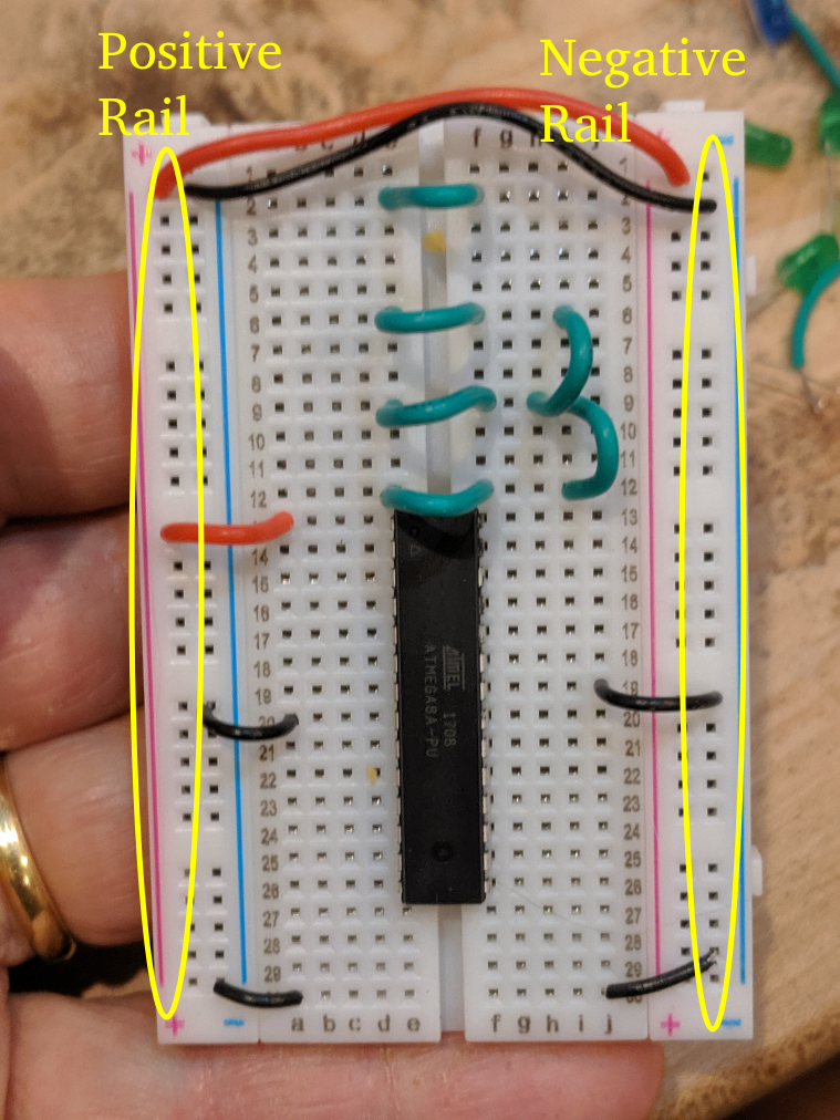
To the left and right of the main breadboard are two power supply rails. The holes in the red column, labelled "+" at the top and bottom, are connected together by a long wire. Similarly, the holes in the blue column, labelled "-", are connected together by a wire. There are no breaks in these wires. The top hole is connected all the way down to the bottom . It is convenient to connect our power packs to these columns and to use them as power for the components in our circuit. This is because there are often many connections to the two sides of a power supply in any given circuit, including this one. So having these rails makes things cleaner.
Here is a picture of the board with one positive rail and one negative rail highlighted. Both the left and the right side each have a positive rail, shown by the red "+" sign and the long red bar, and both the left and right side have a negative rail, shown by the blue "-" sign and long blue bar.
Without further ado, let's assemble the kit!
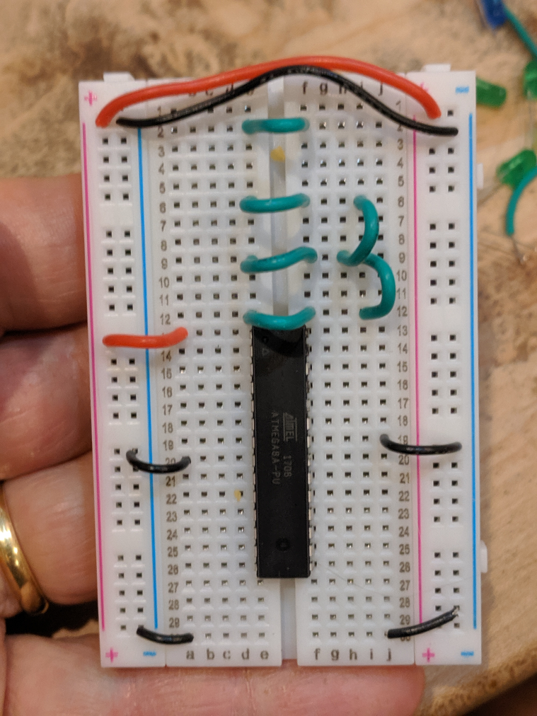
Steps 1-13: Install Wires
Install the Long and Short wires. These are different from the Jumper wires as they have no special plug on each end. Here how your board should look after step 13:
Steps 14-19: Install Resistors, Jumpers, and 2 LEDs
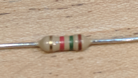
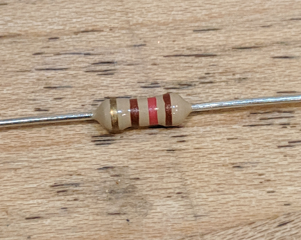
In this series of steps, you'll be installing your first components: the 1.5k ohm and 120 ohm resistors. It doesn't matter which end of the resistors goes in which hole. The resistor works the same in either direction. It is important to use the correct resistor for each location. The resistors have 4 or 5 color bands on them. The 4 band 1.5k ohm resistor is colored with brown, green, red, and gold bands. The 4 band 120 ohm resistor is colored with brown, red, brown and gold bands. If they have 5 color bands, then the 1.5k ohm is colored brown, green, black, brown, and (probably) brown. The 120 ohm is colored brown, red, black, black, and (probably) brown. The "(probably) brown" bands are not critical in color.
|
|
|
| 1.5k ohm resistor | 120 ohm resistor |
The 10 cm jumper wires look like this. Notice the special tips at each end:
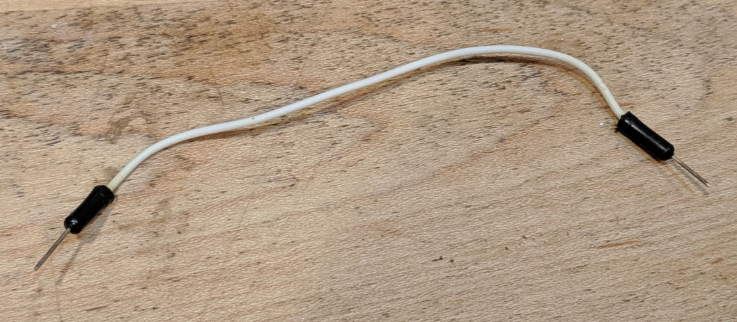
We like to reserve red and black for connections to the power rails, but unfortunately we may need to use some of those colored jumper wires for signals to the LEDs. Ultimately it's not important what color wire you use.
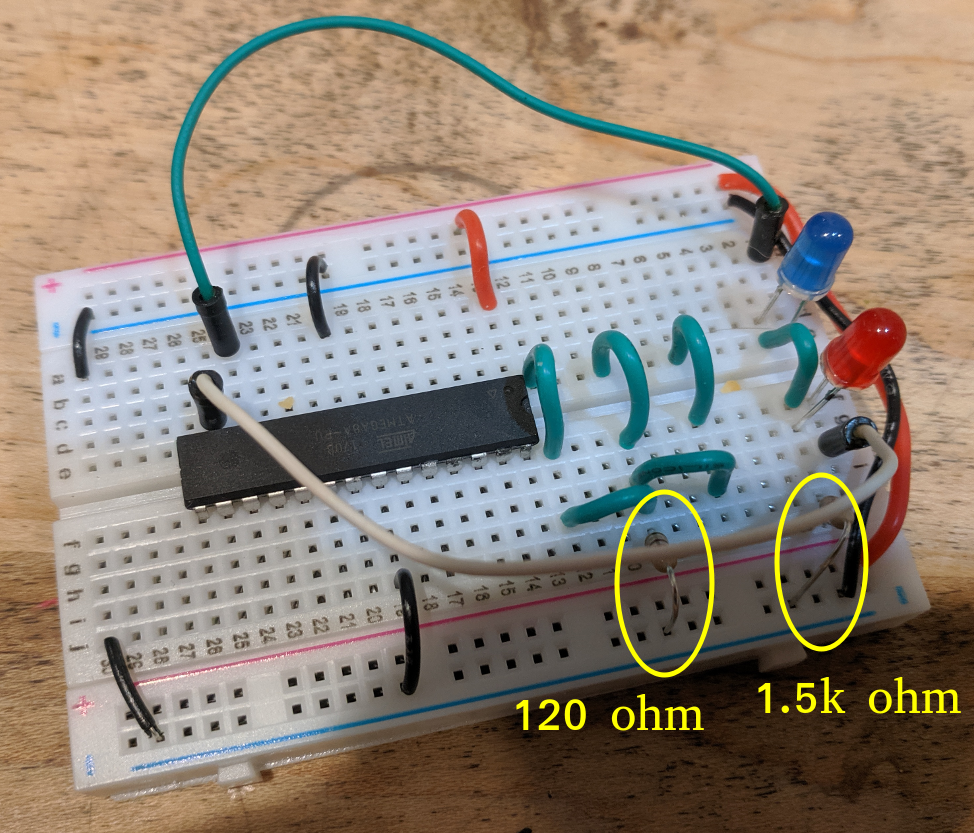
Steps 14-19: Install Resistors, Jumpers, and 2 LEDs, continued...
Here's what your board should look like after installing the jumpers and LED's for this step. Note that I've circled the proper locations for the resistors.
Steps 20-22: First Battery Test
Install the batteries in the battery pack, making sure to put the flat end of each battery (without the little bump) against the spring. Connect the battery pack: The red wire into one of the holes in the + column, the black wire into one of the holes in the - column. Since all the holes in a column are connected by a metal wire inside, it doesn't matter which hole you use.
After you plug in the battery, you should see the LEDs blink a few times. This is a self-test. If they do not blink, remove the battery power. Check your wiring and try again.
Whenever the battery pack is not plugged in, remove one of the batteries. This will prevent an accidental short circuit by touching the ends of the battery wires together. It is not necessary to remove them all.
Steps 23-30: Jumpers and Resistor
Now, starting with line 23, install more jumpers. Here is what the board will look like after line 25 has been completed:
Complete the 4 more jumper wires and 1 resistor in lines 26-30 for this section.
Steps 31-37: Dice LEDs
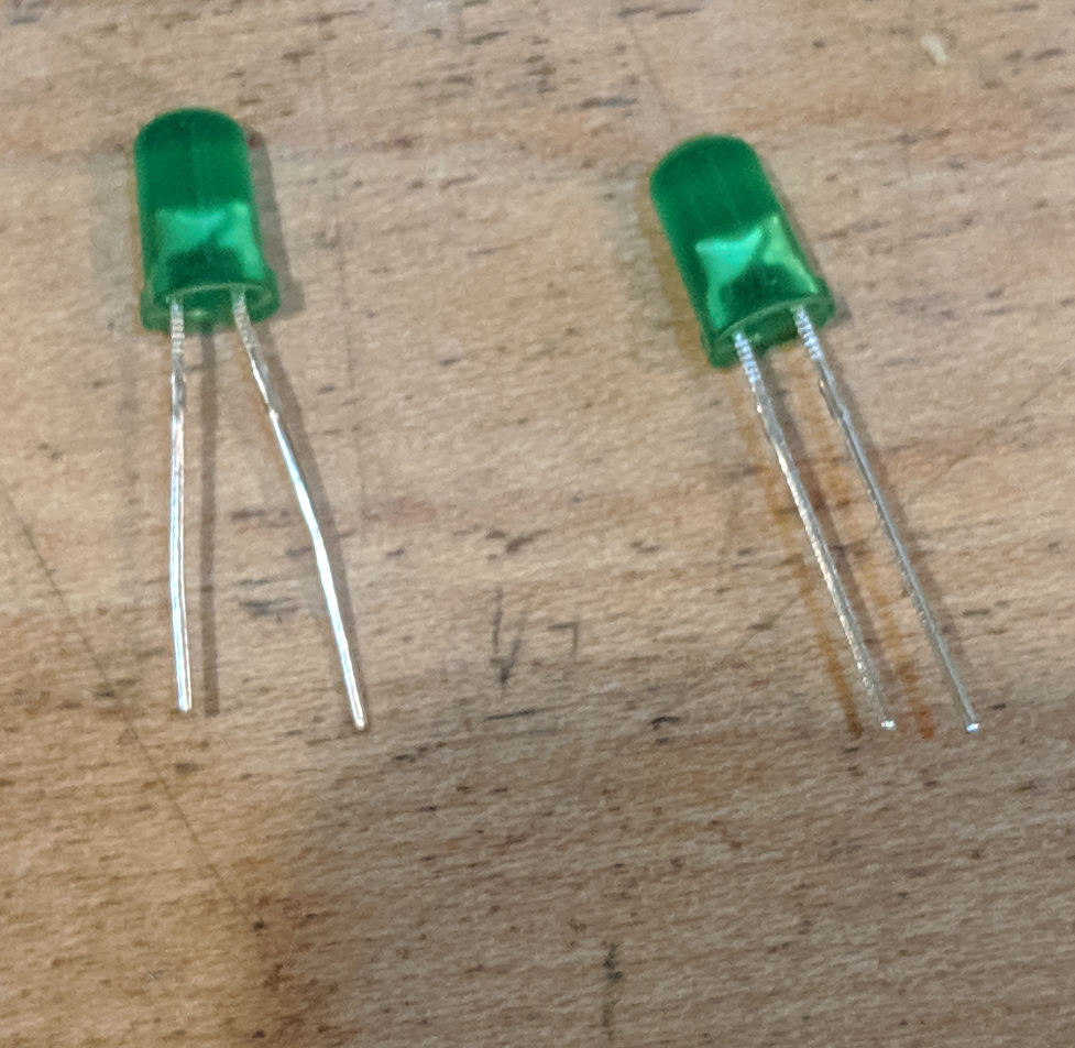
Now it's time to install the majority of the dice LEDs. Look at the wire leads ("legs") of the LEDs. One is longer than the other. See the LED on the right in the picture below. There, the rightmost lead is longer.
Insert the LED with the long and short leads going into the holes indicated on the Wiring Instruction Table. For the LED on step 31, which is connected from 9d to 7e, it would be helpful to carefully bend the leads as show in the picture on the left, so it will stand more straight.
Steps 38-40: Second Battery Test
Again, install the batteries in the battery pack, making sure to put the flat end of each battery (without the little bump) against the spring. Connect the battery pack: The red wire into one of the holes in the + column, the black wire into one of the holes in the - column.
And again, you should see the LEDs blink a few times. This is a self-test. If they do not blink, remove the battery power. Check your wiring and try again. Especially check the LEDs; if you put them in backwards, they won't light. You might try reversing one of the LEDs to see if maybe you put any in backwards. Unplug one of the battery wires and plug it in again. This will make the circuit go through its self-test again, and it will blink all of the LEDs.
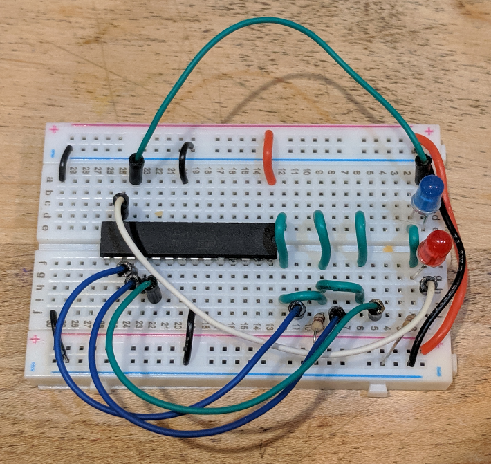
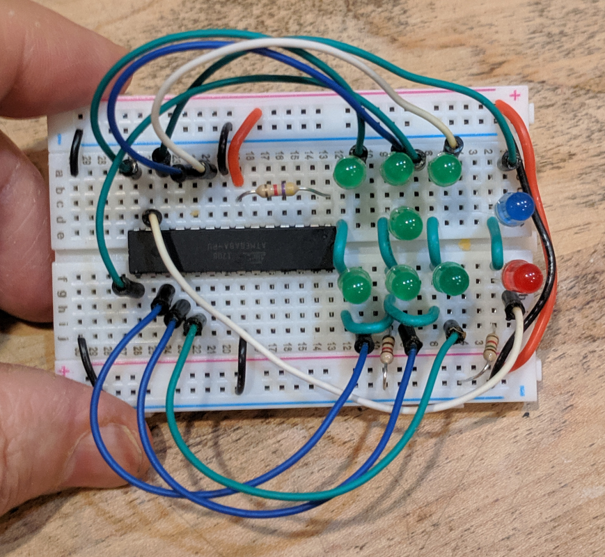
Always be careful to properly plug the black and red wires into the proper column on the power rails. The red goes into the red rail, the black goes into the blue rail. Here is what your circuit will look like after plugging in all the LEDs:
Steps 41-47: Capacitors, Switches, and Final Test!
Install the remaining parts, from step 41 to 45. The electrolytic capacitor has a positive lead and a negative lead. The negative lead is labeled, similarly to this:
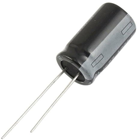
It's important to insert it in the proper direction. Make sure the "-" side goes into the blue column on the power supply rails.
Insert the switches.
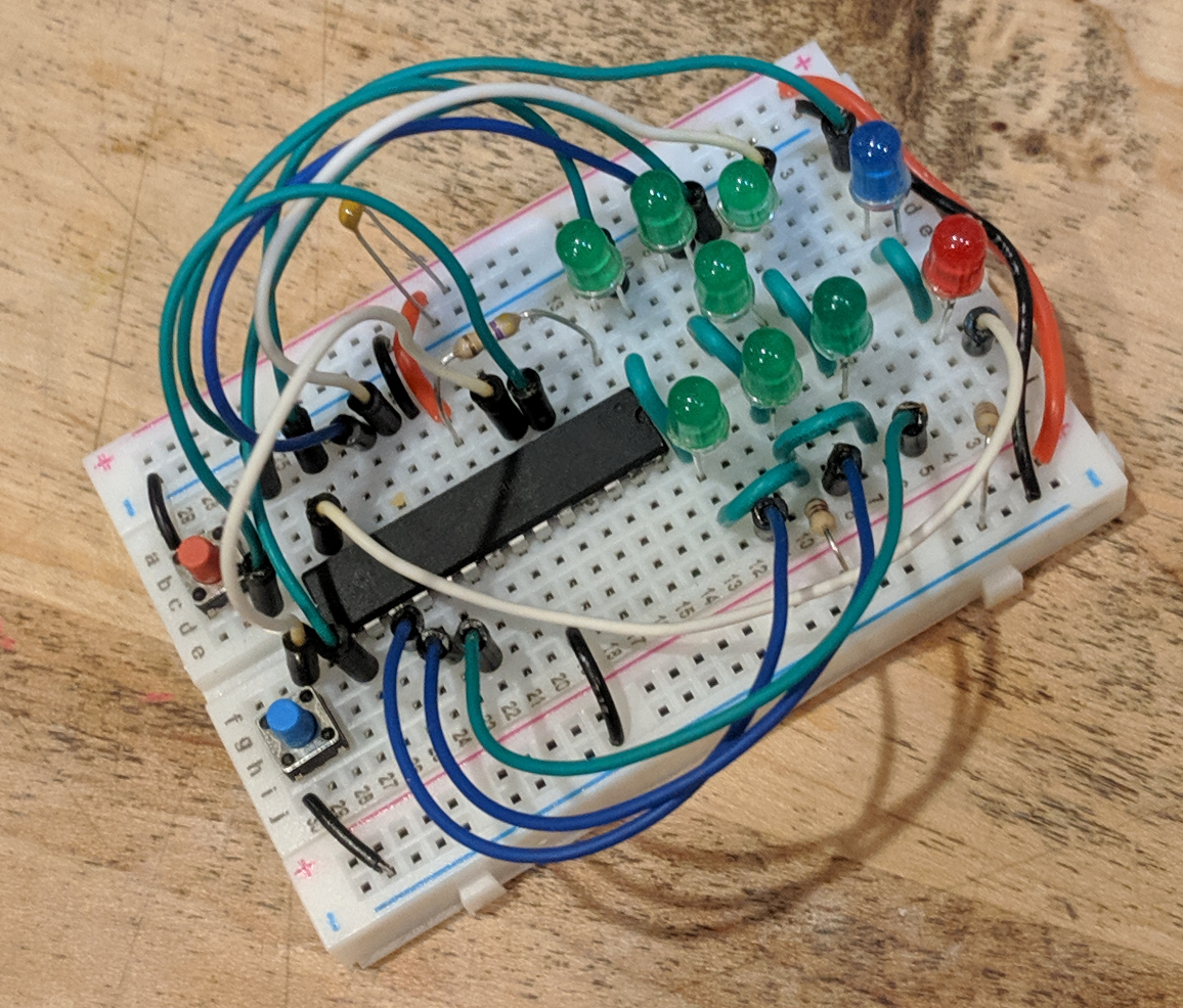
Congratulations, the circuit is all wired up! Here's what it looks like when it's done:
Using the Dice
Insert all the batteries in the battery pack, and plug it in. The LEDs should blink again, then all will be off.
Press one of the switches. You should see the dice blink in a pattern, then- depending on which switch you pressed- settle down to look like the face of a die, with a number 1-6 lit on the front, or one of the two LEDs at the top will light, to indicate either a "heads" or a "tails".
You can roll or flip as many times as you want! Play games with your friends! Impress your parents! Go online and read all about microcontrollers, and study the source code! Become a computer scientist! The possibilities are endless.
Support
Having trouble getting it to work? Send email to support@schwager.com. Tell me what's going wrong, and I'll try to help you figure it out. A picture would probably be helpful, if you can send one.
If you have any missing parts please send a list along with your address and I'll send you replacements.
Theory of Operation
Your ATmega8a dice kit uses a "microcontroller" as the brains of its operation. A microcontroller is a small, inexpensive computer capable of being programmed to do many things. It has built-in memory and a number of helper circuits so that it can read switches or other indicators, it can output signals to LEDs or other digital devices, and it can control motors or create sounds or perform any of a number of other tasks limited only by your imagination and the size of the built-in memory.
For this kit, the program is located at https://github.com/GreyGnome/dice/tree/master/dice_atmega8 . You are free to download or view the source code, and use it for any purpose.
After pressing the "roll" button, the dice works by using a pseudo-random number generator to choose a number between 1 and 6. A pseudo-random number generator is a mathematical operation or series of operations that produce numbers time and time again that (hopefully) look completely random with respect to each other. This project uses a pseudo-random number generator that's delivered with the C language which was used to write the program. Although modern pseudo-random number generators are generally pretty good, all pseudo-random generators come with issues: You must "seed" them with a value that is itself hopefully random, and which is used as a basis for starting to generate pseudo-random numbers again and again. Because pseudo-random number generators are mathematical operations, they will create the same sequence of numbers every time a certain seed is used. This is a significant drawback to pseudo-random number generation, and it's an issue that engineers go to great pains to try and compensate for. Using the same seed every time the device starts means that you'll see the same sequence of numbers- hardly random at all!
So generating a random seed is critical. If it were easy, then there would be no need for pseudo-random number generators. This kit generates a random seed as follows: Inside the microcontroller is a counter that goes from 0 to 255 very quickly- it counts up 4000 times per second. Picking an exact number would be almost impossible. So as soon as you press a 'roll' or 'flip' switch, the counter is read. This number is used as a seed. So now we'll have one of 256 sequences of numbers- pretty good, but remember, it's only 256. Can we do better?
Yes. The very next time you press a button, the next counter number is read. This number is then combined with the previous number in a rather complicated way *, to get a seed that's between 0 and 65535.
This repeats two more times, the first time the seed is one of 16 million values, and finally the second time the pseudo-random number generator is seeded with one of 4 billion values! 4 billion (actually 4,294,967,296) is the largest number possible to use for a seed. But that's a lot of numbers, and would impossible to guess which was used. So the sequence of numbers created by the pseudo-random number generator should be good and non-guessable.
* How is it done? Technically, it's shifted left by 8 (which is equivalent to multiplying by 256), then added to the current reading to get a number between 0 and 65535.
Thanks
A special thank you to teachers everywhere, especially those that live on in my heart and mind, wherever you may be today. Without you, we couldn't make fun stuff!
And a shout out to Mr. Wanner (my High School electronics teacher). Always remember, if it's not working:
- Check to make sure it's plugged in.
- Check to make sure it's turned on.
- Check the fuses (if any).
OK? Go!
...Thanks, Mr. Wanner!
License
Copyright 2019 Michael Anthony Schwager. This document is distributed under terms of the Creative Commons Attribution 4.0 International Public License. See https://creativecommons.org/licenses/by/4.0/legalcode. The license also can be found at the source website, https://github.com/GreyGnome/dice/tree/master/dice_atmega8.